
Hi everyone! I’m the site manager at GOOD-KNIFE, working with our engineers to share practical guides on heavy-duty blades, shredder knives, and custom moulds.

What Are You Looking For?
Request a Quote

Hi everyone! I’m the site manager at GOOD-KNIFE, working with our engineers to share practical guides on heavy-duty blades, shredder knives, and custom moulds.
Quick answer: A briquetting press mould set is designed as one system. Cavity geometry, punch geometry and concentricity come first; the tool steel and hardness window come second; the feed material is the fixed input for all of them.
A briquetting press mould set is designed as one system: the die or mould cavity sets the briquette's final density and its behaviour on ejection, the punch transfers press force into that cavity, and the guide sleeve holds the punch concentric with the bore, stroke after stroke. The order of decisions that works is cavity geometry, then punch geometry and working length, then concentricity, then tool steel and hardness window, then cavity finish and heat treatment - with the material being pressed fixed as the input for every one of them. A set specified in another order usually ends up with one component carrying a load the other two were designed to share.
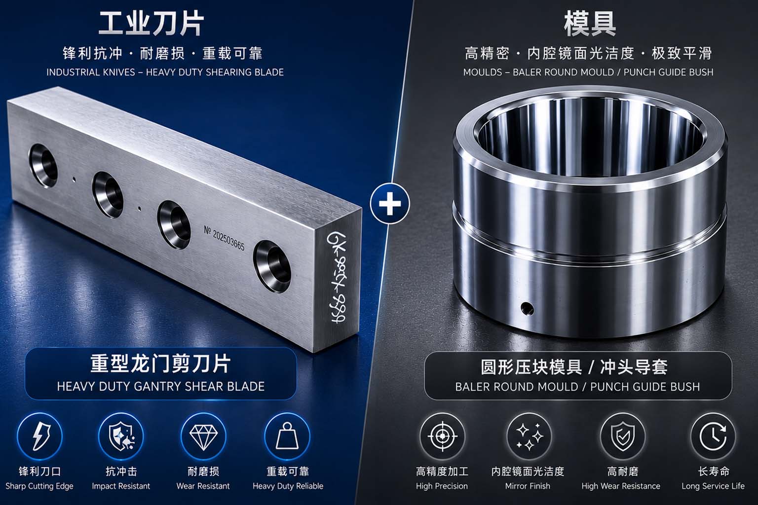
Three components do the work, and each one is specified against a different load:
The same three-part logic applies to metal chip briquette lines, cast iron swarf, shredded metal and biomass briquetting machines. What changes between applications is cavity geometry, bore finish and the hardness window the tool steel is treated to. How each component fails, and which symptoms appear before visible damage does, is covered in why briquetting press moulds and punches wear out; this guide stays upstream of that, on the design decisions that prevent it.
| Component | Load it carries | What the design has to protect |
|---|---|---|
| Die or mould | Sliding contact with abrasive feed under compression | Bore geometry, cavity edge radius, bore surface finish |
| Punch | Repeated compressive load, thousands of strokes per shift | Face geometry, edge support, working length allowance |
| Guide sleeve or bushing | Lateral and off-axis movement, no pressing load | Clearance, concentricity, galling resistance |
Cavity work is where a briquette line is won or lost, because the cavity decides three things at once: the density the briquette reaches, the force needed to eject it, and the way the bore wears while it does so.
Bore diameter and cavity depth. Together these set the compression the feed undergoes between fill and finished briquette. A cavity sized for the target briquette but not for the compressibility of the feed produces briquettes that look correct leaving the press and break in the container.
Cavity taper and relief. A cavity without relief on the exit side holds the briquette and raises ejection force, which appears as scoring on the bore and rising press pressure for the same stroke.
Cavity edge radius. The edge where the bore meets the face of the die controls briquette edge quality. An edge radius that has worn open produces flash and torn edges long before the bore itself is out of tolerance.
Bore surface finish. Finish controls friction, and friction controls both ejection force and the rate at which the bore wears. A cavity ground to a consistent finish wears evenly; a cavity with a polished band in the middle and a rougher entry wears asymmetrically from the first shift.
| Cavity parameter | What it controls | Symptom when it is wrong |
|---|---|---|
| Bore diameter and depth | Compression ratio and final density | Briquettes that crumble or that will not release |
| Cavity taper and relief | Ejection force and bore friction | Sticking ejection, squealing, rising press pressure |
| Cavity edge radius | Briquette edge quality | Flash and torn edges on finished briquettes |
| Bore surface finish | Friction and wear rate | Uneven bore wear and premature clearance growth |
| Number and layout of cavities | Load distribution across the punch face | Uneven punch face wear concentrated on one side |
The punch is usually chosen last and blamed first. Three design details decide how it performs.
Face geometry. A flat face with a controlled edge radius spreads load across the cavity; a crowned or lipped face concentrates it at the rim. Where face geometry has been altered by years of regrinding without being restored, the punch is effectively a different tool from the one the line was commissioned with.
Working length and regrind allowance. Working length is the part of the design that decides service cycles, because it is what remains to be ground away between services. A punch ordered to its minimum dimension can be perfectly accurate on day one and unusable after two regrinds.
Edge support. The transition between the punch face and its flank needs enough section to carry compressive load without cracking at the corner. This is the direct trade-off between wear resistance and toughness, and it is set by hardness as much as by geometry.
Punch-to-bore clearance. Clearance is a design parameter, not a tolerance to be tightened for safety. Too tight and the punch scores the bore on the way in; too loose and compression is lost and the punch edge takes the shear.
The guide sleeve carries no pressing load, and that is what makes it easy to leave out of the specification. It holds the punch on the centre line of the bore, so every increment of play becomes lateral movement at the punch face - and lateral movement becomes uneven wear on both components at once.
Two design decisions matter here. Self-lubricating sleeves keep clearance stable for longer under the heat and dust of continuous pressing, and sleeve bore size and length should be specified against the press's actual stroke rather than against a nominal dimension. Punch guide sleeves for briquetting presses are specified by bore diameter, length and interference or clearance, and they belong in the same replacement decision as the punch.
The practical rule: when wear appears on one side of the punch or one side of the bore, check the sleeve before blaming the die, because a matched set installed into a worn sleeve reproduces the previous wear pattern within a few weeks.
Grade, hardness and heat treatment have to agree with each other, and all three have to agree with the feed.
Tool steel grade. Abrasive feed - mill scale, foundry sand, cast iron swarf - pushes the choice toward carbide-forming tool steels with high wear resistance. Heavier or denser feed pushes the choice toward grades with more toughness, because a cavity that cracks costs more than a cavity that wears.
Hardness window. Too soft and the bore scores quickly under abrasive feed; too hard and the punch edge chips under compressive load. The window is set by the material being pressed, the cavity geometry and the load the press actually generates. The underlying balance is the same one described in wear resistance versus impact toughness.
Cavity finish and heat treatment. Precision grinding reduces friction and lowers ejection force; controlled vacuum heat treatment with a proper tempering cycle produces uniform hardness and dimensional stability across the whole tool. Those process choices, and the effect they have on service life, are set out in how heat treatment and manufacturing quality extend tool life.
| Feed being pressed | Dominant load | What the specification should favour |
|---|---|---|
| Metal chips and machining swarf | Abrasion under moderate compression | Wear-resistant carbide-forming steel, tighter bore finish, hardness toward the upper end of the window |
| Cast iron swarf and foundry sand contamination | Heavy abrasion | Maximum wear resistance, disciplined clearance control, sleeve condition checked at every service |
| Dense or oversized feed, mixed scrap | Compression and impact | Toughness-first grade with generous edge support, matched to a punch of comparable hardness |
| Biomass and other soft, bulky feed | Friction and heat under lighter load | Cavity profile and finish tuned for release, hardness chosen for wear rather than impact |
Lines that press more than one material tend to make the same compromise: one grade chosen for the worst feed they might meet, applied to punch and die alike. The result is predictable. Abrasion-dominated feeds wear the die faster than the punch; impact-dominated feeds crack the punch while the bore is still in tolerance; and the set retires when the first component goes, with the other two still serviceable.
A matched set - briquetting press dies and punches selected for the same load and abrasion profile - keeps wear rates balanced so punch, die and sleeve reach their limits at roughly the same time. When you specify tooling as a complete set, briquetting moulds are best selected this way, with clearance, hardness and geometry chosen together rather than part by part.
Most plants that briquette metal chips shear or shred the same material first, and the tooling on both sides of the process is specified against the same inputs: what is being processed, how abrasive it is, and what loads the machine generates.
On the shearing side, scrap shear blades are specified around clearance and edge toughness, and the mechanisms behind a blade that retires early are set out in the science behind fast wear of scrap shear blades. Upstream again, shredder blades and the shredder knives and spacers that hold them at the right clearance decide the size and consistency of the feed that reaches the press - the mechanics of which are covered in how industrial shredder blades cut metal.
Specifying all three families against one feed description is what stops a plant from optimising a single machine stage while feeding the next one something it was never designed for.
These inputs are settled before a drawing is issued. The separate, part-level list that a supplier needs in order to quote accurately against that drawing is set out in what to send us for an accurate replacement quote.
| Design input | What has to be defined | Why it changes the design |
|---|---|---|
| Feed material and particle size | Material type, chip or particle size, moisture, contamination | Sets compression ratio, cavity profile and the abrasion class the steel has to resist |
| Target briquette size and density | Finished dimensions, weight, handling method, drop strength | Sets cavity volume, cavity count and ejection arrangement |
| Press data | Model, rated tonnage, stroke length, strokes per minute, ejection arrangement | Sets punch working length, load per cavity and where clearance has to be held |
| Concentricity requirement | Sleeve type, clearance class, guide length | Sets the sleeve specification and the inspection routine that keeps it true |
| Current tooling record | Grade and hardness in use if known, tonnage per set, failure pattern | Turns the specification from a catalogue choice into a response to measured wear |
| Regrind policy | Number of regrinds planned, minimum working length | Sets the allowance that has to be left in punch and bore on day one |
Cavity count follows the press. The number of cavities should spread the available pressing load across the punch face without dropping the load per cavity below what the feed needs to reach density. Line throughput and briquette weight per stroke decide the count; the cavity profile then has to be matched to the feed rather than copied from a similar line.
Not automatically. Both are chosen against the load each carries: the die sees sliding abrasion, the punch sees repeated compression. Making the punch harder than the application needs usually moves the failure from wear to chipping, and a chipped edge then damages the bore it runs in.
Only within the material allowance left in the bore. Re-cutting removes material, so a profile change is viable only while the bore is still above its minimum allowable dimension and the body is crack-free. A die that has already been reground several times may have no allowance left for a profile change.
Because clearance opens gradually. As the bore grows, the punch no longer develops full compression, so briquettes come out lighter long before the surface shows scoring. That is why density, ejection behaviour and press pressure are more useful early indicators than visual inspection alone.
Consistent rather than absolute. The important property is a uniform finish along the working length, because a cavity with mixed finishes wears unevenly from the first shift. The finish to specify follows the feed: abrasive, sticky materials benefit from a finer and more uniform bore than dry, free-flowing ones.
Briquetting tooling is specified, not simply sized. Fix the cavity geometry against the feed, give the punch enough working length to be reground, hold concentricity as a design requirement through the guide sleeve, and set the hardness window from the load the press actually generates rather than from a number carried over from another line.
GOOD-KNIFE works with briquetting and metal processing plants on both sides of this decision: selecting moulds, punches and guide sleeves as a matched set, and matching material, hardness and geometry to the feed and press conditions a line actually runs. If you are specifying a new set, or replacing one that retires too early, send us your press details, the material being pressed, your current drawing or measured dimensions - and photographs of how the last set failed. Contact our engineering team to have the tool set reviewed against your operating conditions.
Leave A Message
Home
products
contact